Appendix C - Canonical Reference Diagrams (Normative)
These diagrams define the minimum architectural semantics required to reason about ZKS compliance. Any implementation claiming ZKS compliance SHALL be mappable to these diagrams without ambiguity.
Diagram 1 - ZKS Logical Component Model & Sovereignty Boundary
Purpose
This diagram defines:
- the primary sovereignty boundary,
- the location of decryptability,
- and the separation between user-controlled and third-party components.
This is the single most important diagram in the entire standard.
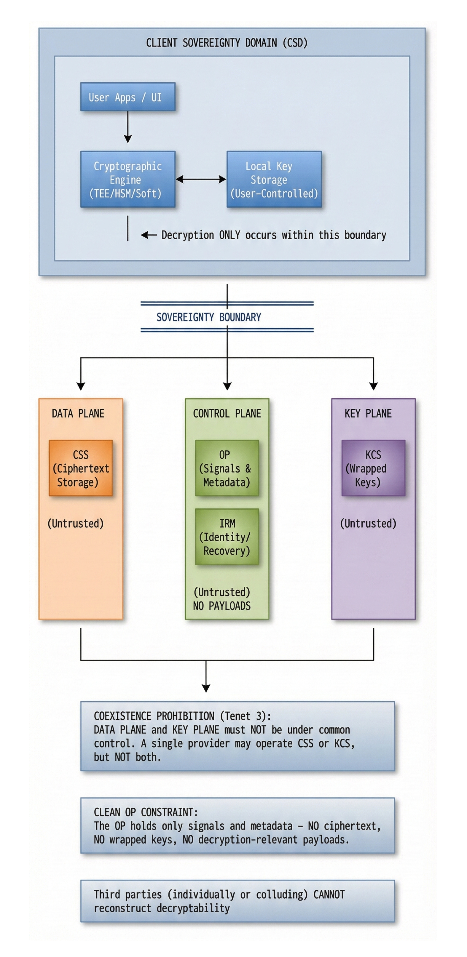
Diagram 1A - Reference Diagram (Normative)
Normative Interpretation
- All decryption occurs exclusively inside the CSD.
- The sovereignty boundary separates decryptability from all third parties.
- CSS, OP, KCS, and IRM are explicitly outside the sovereignty boundary.
- No component outside the boundary may:
- reconstruct,
- derive,
- obtain,
- intercept,
- or revoke decryptability (given ciphertext availability).
- Optional components (KCS, IRM) do not change the boundary.
Any system that requires decryptability to cross this boundary is not ZKS-compliant.
Diagram 2 - ZKS Planes and Channels Separation Model
Purpose
This diagram shows how planes and channels are separated so that no intermediary can co-locate:
- ciphertext,
- unwrapping capability,
- and authorization.
This diagram directly supports:
- Tenet 3 (Separation),
- Tenet 4 (Multi-Intermediary Incapability),
- Section 3.3 (Planes),
- and Section 3.6 (Metadata minimization).
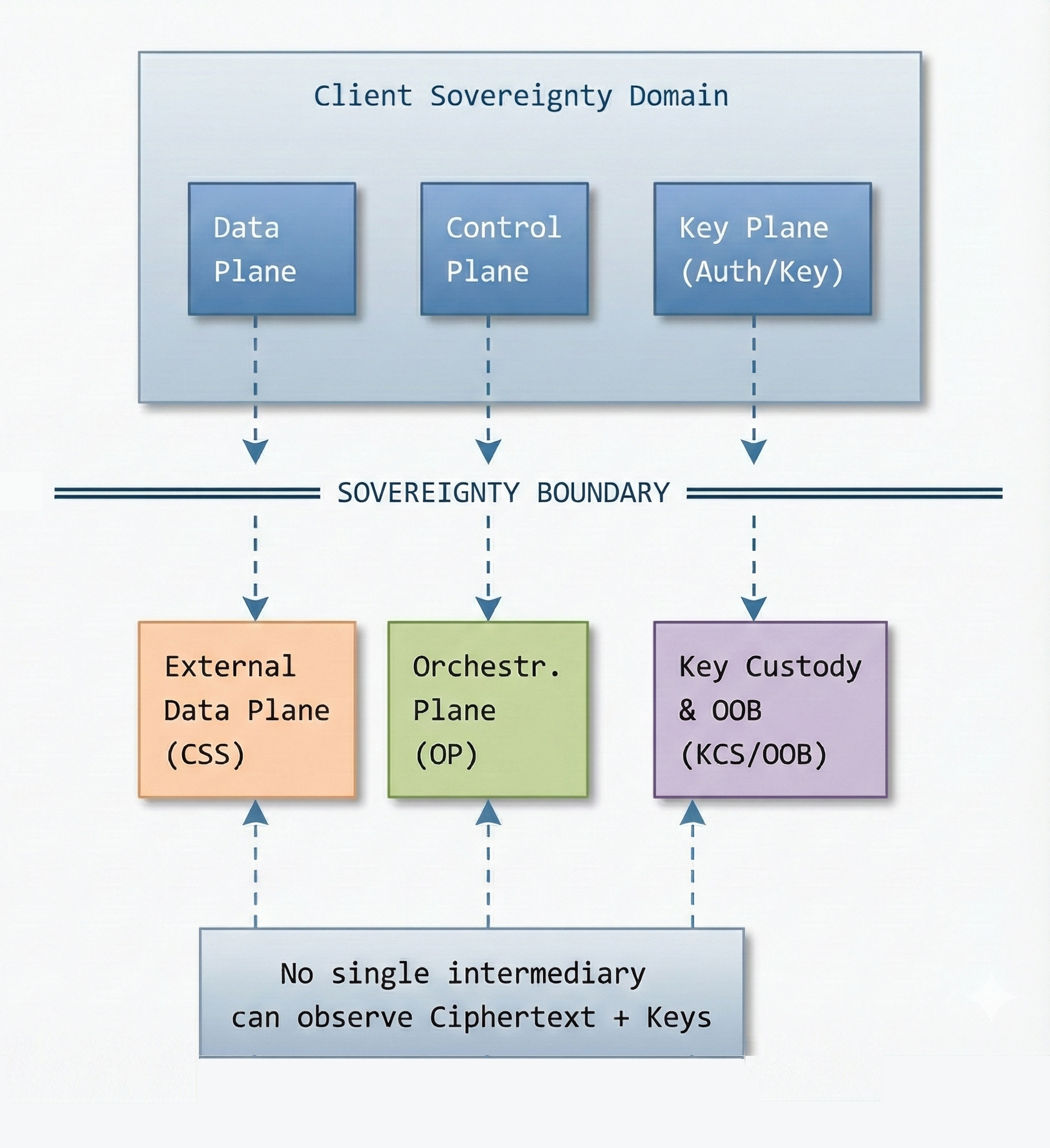
Diagram 2A - Reference Diagram (Normative)
Normative Interpretation
- Vertical Separation: Planes are logically independent. The Data Plane MUST NOT intersect with the Key Plane outside the CSD.
- No Cross-Talk: The Orchestration Plane (OP) MUST NOT process ciphertext from the Data Plane or keys from the Key Plane.
- The OOB Plane: Is independent of the Data Plane and strengthens user control.
- A system where any single intermediary can observe Ciphertext + Keys is not ZKS-compliant.
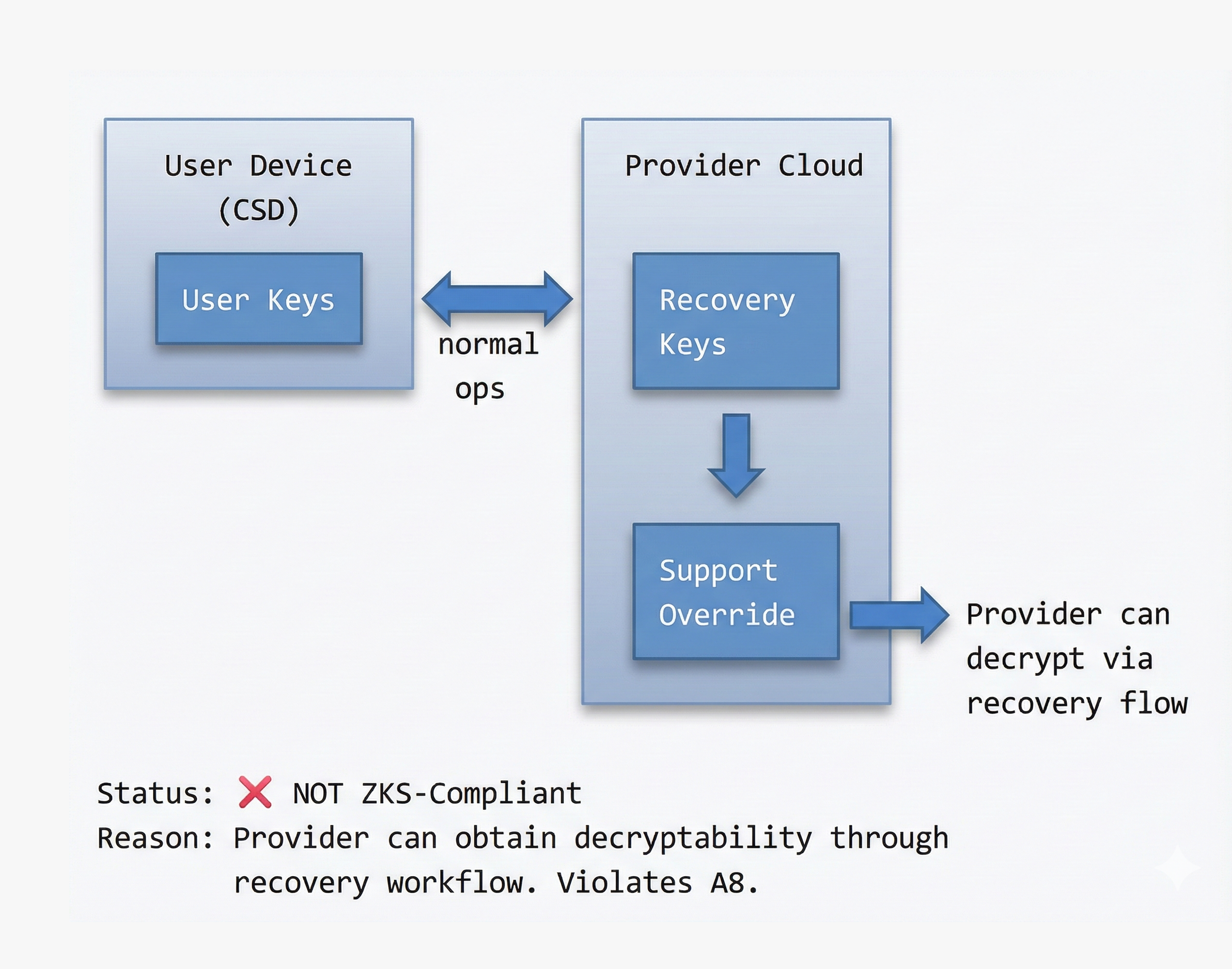
Diagram 3 - Prohibited Architectures (Informative but Critical)
These diagrams are useful in audits and competitor discussions.
Diagram 3A - Anti-Pattern: Centralized Provider Control
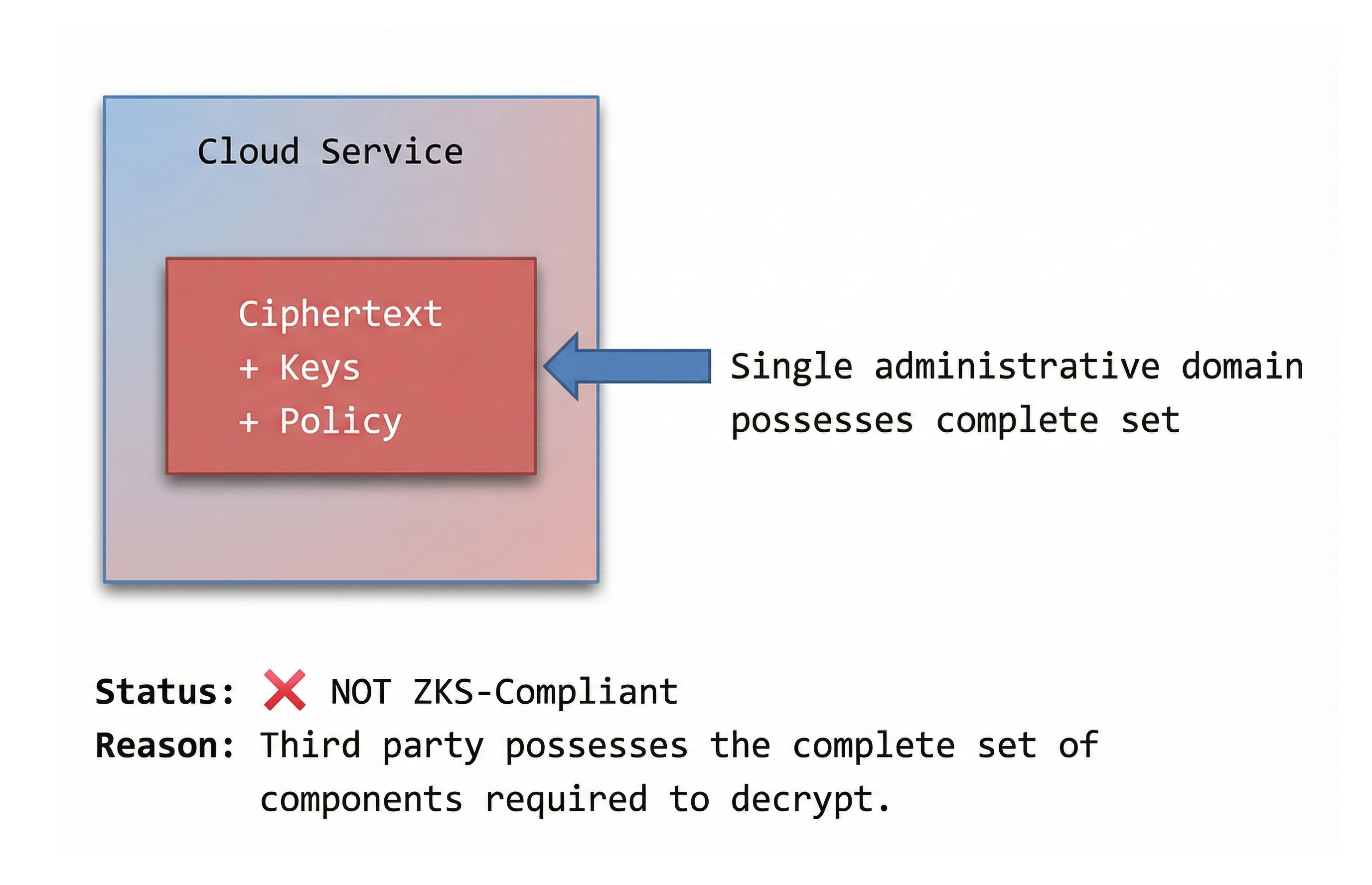
Diagram 3B - Anti-Pattern: Provider-Held Recovery Keys